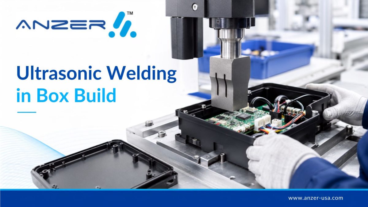
Ultrasonic Welding for Electronic Enclosures in Box Build Assembly: An OEM Design & RFQ Guide
Ultrasonic welding can be an effective way to permanently join compatible thermoplastic electronic enclosures, but the weld cannot be treated as a final assembly step that engineering decides on after the PCB and housing are finished.
In an electronic box build, the enclosure, plastic material, joint geometry, PCB assembly, wire routing, connectors, sensors, fixture support, vibration-sensitive components, sealing requirement and final test strategy all interact.
For an OEM, the real question is therefore not simply “Can this enclosure be ultrasonically welded?”
The better question is:
“Can this complete electronic assembly be designed, welded and tested repeatedly without compromising the PCBA, enclosure, sealing requirement or final system performance?”
That distinction should be addressed during DFM, not after tooling release.
ANZER approaches these projects from the complete box build assembly services perspective, where PCBAs, wiring, connectors, mechanical hardware, enclosures, firmware requirements, testing and final manufacturing documentation must work together.
What Is Ultrasonic Welding for Electronic Enclosures?
Ultrasonic welding uses high-frequency mechanical vibration and pressure to create a joint between compatible materials.
For thermoplastic enclosures, energy is transferred through the part to the joining interface. Localized heating softens or melts material at the joint. Pressure is maintained as the interface consolidates and solidifies.
TWI provides a detailed technical explanation of the ultrasonic welding process and notes its use in electrical, electronic, medical and other manufacturing applications.
For electronics manufacturers, the attraction is straightforward. A properly engineered ultrasonic joint may provide a permanent enclosure without requiring conventional screws or an adhesive bead around the entire housing.
But “properly engineered” is the important part.
The welding process begins with product design.
Where Ultrasonic Welding Fits Into a Box Build
A box build moves beyond PCB assembly and combines the electronic and mechanical elements into the final system.
Depending on the product, that may include:
- PCB assemblies
- Wire harnesses and cable assemblies
- Connectors
- Displays
- Sensors
- Buttons and switches
- Brackets and mechanical hardware
- Plastic or metal enclosure components
- Firmware loading
- Labels and serialization
- Functional testing
- Environmental protection processes
- Final inspection and packaging
ANZER’s wire harness and cable assembly capabilities can also become important because enclosure closure determines connector location, wire routing, bend radius, strain relief and access during final assembly.
If ultrasonic welding is selected for a plastic enclosure, the weld process becomes another interface in this system.
It cannot be designed independently from everything inside the box.
Why OEMs Consider Ultrasonic Welding for Plastic Electronic Enclosures
For the correct application, ultrasonic welding can offer several manufacturing advantages.
Permanent Assembly
The process can produce a permanent plastic-to-plastic joint.
That can be valuable when the finished product is not intended for routine field disassembly.
No Separate Fastener Around the Weld Joint
Traditional enclosure assembly may require screws, inserts or other mechanical fastening hardware.
An ultrasonic weld can remove some of those components when the product architecture permits it.
This should be evaluated at the complete BOM and serviceability level, rather than simply comparing one fastening operation with another.
No Adhesive Cure Step at the Weld Interface
When ultrasonic welding replaces an adhesive joint, the manufacturing plan no longer depends on that particular adhesive dispensing and cure operation.
However, that does not automatically mean ultrasonic welding is the lower-risk process.
It replaces adhesive-process risks with different requirements involving material compatibility, joint design, horn access, fixtures, vibration and weld validation.
Controlled Enclosure Joining
When materials, geometry, tooling and process parameters are validated, ultrasonic welding can support repeatable production.
That repeatability begins with a weldable enclosure.
The Most Important Decision Happens Before the Enclosure Tool Is Released
One of the most expensive ultrasonic-welding mistakes is selecting the process after the plastic parts have already been designed.
The enclosure needs to be designed around the joining method.
TWI’s ultrasonic welding joint-design guidance emphasizes that successful welding depends strongly on component design and the surfaces being joined.
For OEM teams, the DFM review should examine at least the following.
| Design Area | What Engineering Should Confirm |
|---|---|
| Plastic material | Exact resin and grade intended for production |
| Joint geometry | Appropriate weld-joint architecture for material and requirements |
| Alignment | Housing halves locate consistently before welding |
| Part stiffness | Enclosure transfers welding energy as intended |
| Wall geometry | Local walls withstand welding and fixture forces |
| Horn access | Welding tool has suitable contact geometry |
| Fixture support | Lower component is adequately supported |
| Weld path | Continuous and manufacturable where required |
| Cosmetic surfaces | Flash or marking risks are understood |
| Internal clearances | PCBAs, batteries, connectors and wiring have adequate clearance |
| Sealing | Leak requirement and test method are defined |
| Verification | Acceptance criteria exist before production |
ANZER’s electronic design for manufacturability process is relevant here because enclosure joining should be considered alongside PCB manufacturability, component placement, assembly sequence and testability.
For a broader enclosure-development review, see ANZER’s guide to electronics enclosure design and DFM.
Energy Directors and Joint Geometry Matter
A common ultrasonic-welding approach uses an energy director, a molded feature that creates a small initial contact area at the joint.
The concentrated contact area helps focus ultrasonic energy where the weld is intended to form.
Other joint architectures may be more appropriate depending on the resin and sealing requirement.
The choice should be based on:
- Polymer characteristics
- Enclosure geometry
- Required joint strength
- Sealing requirements
- Cosmetic expectations
- Part rigidity
- Production tooling
- Welding equipment
- Fixture design
This is one reason the OEM should establish the enclosure joining strategy during DFM.
Adding a weld feature after mold design is substantially different from designing the molded component around the manufacturing process from the beginning.
Material Compatibility Must Be Verified by Exact Resin Grade
“Plastic” is not a sufficient material specification for an ultrasonic-welded enclosure.
Neither is simply saying “ABS,” “polycarbonate,” “nylon,” or another polymer family.
Engineering should control the exact production material specification because welding behavior can be affected by the polymer system and part construction.
Questions to resolve include:
- What exact resin is specified?
- Are both enclosure halves made from compatible materials?
- Are fillers or reinforcements involved?
- Are pigments or additives controlled?
- Is recycled content allowed?
- Has the production material combination actually been evaluated for the selected welding process?
- Does an alternate resin require manufacturing revalidation?
For a box-build supplier, revision control matters here.
Changing the enclosure resin can be a manufacturing-process change, not merely a purchasing substitution.
Ultrasonic Welding Can Affect Sensitive Electronics Inside the Housing
This is one of the most important issues for electronic box builds.
The welding process intentionally introduces high-frequency mechanical vibration into the housing.
Some internal components can be more sensitive to vibration than others, and the amount of vibration reaching the PCBA depends on the product geometry, component position, mounting architecture, fixture, welding parameters and enclosure structure. Technical literature has documented this risk in electronics assemblies.
That means the box-build team should ask:
- Where is the PCBA relative to the weld path?
- How is the PCB mechanically supported?
- Are there vibration-sensitive sensors or components?
- Where are large or mechanically vulnerable components positioned?
- Can the enclosure be welded before sensitive electronics are installed?
- If final welding must occur after installation, has the completed assembly been validated?
- What functional testing is required after welding?
A PCB that passes testing before enclosure closure has not necessarily demonstrated that it will still meet every requirement after the welding operation.
That distinction belongs in the manufacturing plan.
Assembly Sequence Can Be as Important as the Weld Parameters
Consider two simplified manufacturing sequences.
Sequence A: Weld the Housing Before Sensitive Electronics Are Installed
This may reduce vibration exposure to the electronics.
However, the product design must allow the PCBA and other components to be installed afterward.
That is not possible for every enclosure architecture.
Sequence B: Install Electronics, Then Ultrasonically Weld the Housing
This may simplify the final enclosure design or make a complete perimeter weld possible.
But the installed electronics now experience the manufacturing operation.
In that case, validation may need to consider:
- PCBA mounting
- Component vibration sensitivity
- Cable routing
- Connector retention
- Fixture forces
- Post-weld continuity
- Functional performance
- Calibration, where applicable
- Visual inspection
- Leakage or ingress testing when specified
There is no universally correct sequence.
The right sequence is the one validated for the actual product architecture.
Do Not Assume an Ultrasonic Weld Is Automatically Waterproof
This is an important RFQ and engineering distinction.
Ultrasonic welding can be used in applications requiring sealed joints, but the process itself does not make every joint watertight or airtight.
TWI specifically notes that ultrasonic welding does not inherently produce waterproof or airtight joints. Achieving those requirements depends on factors including the plastic shells, weld structure, wall thickness, materials and welding process.
Therefore:
“Ultrasonically welded” is a manufacturing-process description. “Watertight,” “airtight,” or a specified ingress rating is a product-performance requirement. They are not interchangeable.
If enclosure sealing matters, the drawing or product specification should define the actual requirement.
The manufacturing plan should then define how that requirement will be verified.
Depending on the product, verification could involve an approved leak or functional ingress test rather than relying only on visual inspection of the weld line.
Ultrasonic Welding vs. Other Electronic Enclosure Joining Methods
No enclosure joining method is automatically superior.
The correct option depends on the product.
| Method | Reworkability | Main Advantage | Main Engineering Consideration |
|---|---|---|---|
| Ultrasonic welding | Low | Permanent thermoplastic joining without conventional fasteners at the weld | Material, joint, vibration, horn and fixture validation |
| Screws + gasket | High | Serviceable enclosure | Hardware, torque, inserts, gasket compression |
| Adhesive bonding | Usually low | Can support different joint architectures | Dispensing, surface preparation, cure and material compatibility |
| Snap fits | Medium, design dependent | Low part count | Fatigue, retention, tolerance and sealing |
| Potting/encapsulation | Very low | Environmental protection of electronics | Thermal behavior, material compatibility, mass and rework |
| Mechanical clamps | High | Serviceability | Space, hardware, retention and assembly consistency |
Potting deserves special distinction.
Potting is not simply an alternative enclosure weld.
It protects or encapsulates electronic assemblies and introduces different thermal, mechanical and serviceability considerations.
ANZER performs potting and conformal coating in-house. OEMs comparing protective strategies can also review PCB potting vs. conformal coating.
Common Ultrasonic-Welded Box Build Mistakes
Choosing Ultrasonic Welding After Tooling Is Finished
The joint should be designed around the welding process.
Trying to retrofit the process into an enclosure that was never intended for ultrasonic welding can create expensive redesign work.
Treating Material Selection as a Purchasing Decision
The exact enclosure resin is part of the manufacturing process.
A substitution can change weld behavior.
Ignoring the PCBA During Enclosure DFM
The enclosure engineer and PCB engineer should not work independently until final integration.
PCB location, component height, connectors, cable exits and mechanical mounting all affect the box build.
Putting Vibration-Sensitive Components at Risk Without Validation
A design can produce an excellent plastic joint while damaging something inside the housing.
Both outcomes must be evaluated.
Assuming the Weld Creates a Guaranteed Seal
A continuous-looking weld is not a substitute for a defined leak or ingress requirement.
Forgetting Tool and Fixture Access
A CAD model may look manufacturable until the welding horn and fixture are introduced.
Skipping Post-Weld Functional Testing
If the product is welded after the electronics are installed, the manufacturing test plan should account for the operation.
Ignoring Serviceability
A permanent enclosure may be ideal for one product and unacceptable for another.
Before selecting ultrasonic welding, determine whether the device will ever require field repair, battery replacement, recalibration, firmware service or internal inspection.
When Ultrasonic Welding Is a Strong Candidate
Ultrasonic welding deserves serious evaluation when:
- The enclosure uses compatible thermoplastic components
- Permanent closure is acceptable
- The weld can be designed into the enclosure early
- Suitable horn and fixture access is available
- The enclosure geometry can transmit welding energy appropriately
- Weld appearance can meet product requirements
- Sensitive internal electronics can be protected or validated
- The sealing requirement is measurable
- Prototype testing can occur before production release
- The process can be controlled under documented acceptance criteria
When OEMs Should Consider Another Joining Strategy
Review alternative methods when:
- Routine field opening is required
- The enclosure must remain easily serviceable
- Material compatibility is uncertain
- The joint geometry cannot be optimized
- Tool access is limited
- The product contains highly vibration-sensitive electronics that cannot be adequately protected or validated
- The current enclosure tooling cannot support an appropriate weld joint
- Low development volume does not justify the required production tooling
- The sealing requirement is better achieved using another validated enclosure architecture
The decision should come from product requirements, not from process preference.
What Should Be Tested Before Production Release?
For an ultrasonic-welded electronic enclosure, qualification should go beyond “the two halves stayed together.”
The validation plan should be driven by product risk and customer requirements.
Potential areas include:
Weld and Enclosure
- Joint appearance
- Weld completeness
- Part alignment
- Flash limits
- Dimensional change
- Mechanical integrity
Electronic Assembly
- Power-up
- Functional test
- Communications
- Sensor operation
- Connector integrity
- Calibration where applicable
- Electrical test requirements specified by the OEM
Environmental or Sealing Performance
Where required:
- Leak testing
- Ingress verification
- Environmental exposure
- Thermal evaluation
- Product-specific qualification testing
Manufacturing Process
- Fixture repeatability
- Weld-process parameters
- Material revision control
- Assembly sequence
- Inspection criteria
- Reaction plan for failed assemblies
- Traceability requirements
The important point is not to run every possible test.
It is to define the tests that demonstrate that welding has not compromised the requirements of that specific product.
Regulated and High-Reliability Electronics Need More Than a Good Weld
For medical, aerospace and other quality-sensitive programs, the enclosure joint sits inside a larger manufacturing and documentation system.
A buyer should also consider:
- Design revision control
- BOM control
- Material traceability
- Assembly instructions
- Inspection records
- IPC workmanship requirements
- Nonconformance handling
- Test documentation
- Serialization
- Production traceability
- Change control
ANZER is certified to ISO 9001:2015, ISO 13485:2016 and AS9100D and supports IPC Class 2 and Class 3 electronics manufacturing requirements.
OEMs developing medical products can review ANZER’s medical electronics assembly capabilities.
Aerospace OEMs can review ANZER’s aerospace electronics assembly capabilities.
The applicability of any specific standard, qualification or test remains dependent on the individual product and customer requirements.
RFQ Checklist for an Ultrasonic-Welded Electronic Box Build
If your enclosure may use ultrasonic welding, provide the manufacturing team with more than a PCB BOM.
Include:
- Product application and intended environment
- Current product revision
- 3D enclosure files
- Mechanical drawings
- Exact plastic resin specification
- Weld-joint drawing
- Enclosure tolerances
- Cosmetic requirements
- Required sealing or ingress performance
- Acceptance test requirements
- PCBA Gerbers and manufacturing data
- PCB assembly drawing
- BOM and approved manufacturer list
- Internal mechanical layout
- Sensitive-component locations
- Wire-harness drawings
- Connector specifications
- Cable routing requirements
- Firmware-loading requirements
- Functional test procedure
- Calibration requirements, if applicable
- Labeling requirements
- Serialization requirements
- Traceability requirements
- Prototype or production stage
- Expected quantity range
- Packaging requirements
- Regulatory or quality-system requirements
ANZER’s guide on getting a PCB assembly quote can help engineering and purchasing teams prepare the electronic portion of the manufacturing package.
What Should You Ask a Box Build Manufacturer?
Before placing an ultrasonic-welded electronic product with a contract manufacturer, ask questions that cover the complete assembly.
| Question | Why It Matters |
|---|---|
| Will you review the PCBA and enclosure together? | Prevents mechanical and electrical DFM from becoming disconnected |
| How is enclosure material revision controlled? | Material changes may affect joining behavior |
| When does welding occur in the assembly sequence? | Determines exposure of electronics |
| How are vibration-sensitive components evaluated? | Protects the finished PCBA |
| What happens after the enclosure is welded? | Establishes functional verification |
| How is sealing verified? | Prevents unsupported “waterproof” assumptions |
| How are harnesses and connectors controlled? | Final closure can change routing and retention |
| Can prototype lessons transfer into production documents? | Reduces scale-up risk |
| Which records are retained? | Important for traceability and RCA |
| What is the corrective-action process? | Establishes how manufacturing problems are contained and prevented |
These questions tell you more about manufacturing readiness than asking for a piece-price comparison alone.
Where ANZER Fits Into an Ultrasonic-Welded Box Build
ANZER USA is an electronic contract manufacturer based in Akron, Ohio, supporting OEMs from product development and PCB assembly through complete system integration.
Verified capabilities relevant to these programs include:
- SMT, through-hole and mixed-technology PCB assembly
- DFM and DFA support
- Component sourcing
- PCB integration
- Mechanical box-build integration
- Wire harness and cable assembly
- Connectors and hardware integration
- Firmware/software installation requirements
- AOI and X-ray inspection
- ICT and flying-probe testing
- Functional testing
- Burn-in testing
- In-house conformal coating
- In-house potting
- Serialization and labeling
- Packaging
- Prototype and pre-production builds
- ISO 9001:2015
- ISO 13485:2016
- AS9100D
- IPC Class 2 and Class 3 capability
- U.S.-based manufacturing in Akron, Ohio
ANZER also has a 33+ year manufacturing legacy from Western Reserve Controls through the current ANZER organization.
Important Capability Note
Ultrasonic welding is not currently listed among ANZER’s verified in-house manufacturing capabilities.
If your enclosure requires ultrasonic welding, identify that requirement at the beginning of the RFQ.
ANZER can then review the overall electronic box-build requirements and confirm the appropriate manufacturing path before the program is released.
That is more reliable than assuming an enclosure process after PCB assembly, tooling and testing have already been finalized.
Questions OEMs Should Answer Before Requesting a Quote
Before sending an ultrasonic-welded box build RFQ, your engineering and procurement teams should be able to answer five questions:
- What does the enclosure have to accomplish?
Permanent closure, structural retention, ingress resistance, appearance, tamper resistance or another defined requirement? - Has the enclosure been designed for the selected joining process?
Do not assume a standard molded housing is automatically weldable. - What electronics will be inside during welding?
Identify anything that may require vibration-risk evaluation. - How will you know the finished product passed?
Define functional, mechanical and sealing acceptance criteria. - Does your manufacturer understand the entire box build?
The weld, PCBA, harness, connectors, enclosure, firmware and final test should operate as one controlled manufacturing process.
Frequently Asked Questions
Can ultrasonic welding be used for electronic enclosures?
Yes. Ultrasonic welding is used to join compatible thermoplastic components and can be appropriate for electronic housings. The product still needs engineering review for material compatibility, joint geometry, tooling, internal electronics, manufacturing sequence and verification.
Can ultrasonic welding damage a PCB?
It can create a risk for vibration-sensitive electronic components because the manufacturing process transmits high-frequency mechanical vibration through the housing. Component location, mounting, fixture design, product geometry and welding conditions should therefore be evaluated and the finished assembly tested where appropriate.
Is an ultrasonic-welded enclosure waterproof?
Not automatically. Ultrasonic welding can be engineered for sealing applications, but watertight or airtight performance must be defined and verified. TWI specifically cautions that the welding process alone does not inherently guarantee waterproof or airtight performance.
Is ultrasonic welding better than screws or adhesive?
Not universally. Ultrasonic welding is attractive for some permanent thermoplastic assemblies, while screws may be better for serviceability and adhesives may suit different material or geometry requirements. The choice should be based on the complete product requirements.
What should I send ANZER for an ultrasonic-welded box build RFQ?
Send the PCB manufacturing package, BOM, enclosure CAD and drawings, exact plastic specification, weld requirements, internal mechanical layout, wire-harness documentation, firmware requirements, testing criteria, sealing requirements, labeling, traceability requirements and expected production stage. Clearly identify ultrasonic welding as a required or proposed joining process so its manufacturing path can be reviewed before quotation.
Conclusion
Ultrasonic welding can solve an enclosure-assembly problem, but only when it is engineered as part of the complete electronic product.
A successful ultrasonic-welded box build requires coordination between the enclosure, plastic material, weld joint, PCB assembly, sensitive components, wiring, connectors, assembly sequence, tooling, fixtures, sealing requirement and final test.
OEMs reduce manufacturing risk when these decisions happen during DFM rather than after the enclosure tool, PCB and production process are already locked.
If you are developing a new electronic product or moving an existing design toward production, ANZER can review the complete box build assembly requirements, including PCBAs, wiring, enclosure integration, DFM, testing and documentation.