It is lessor know that there are distinctions between a wiring harness and a cable assembly in the electronic manufacturing industry. The terminologies are often interchanged, but the two are significantly different. Consider this answer (ANZER) to help facilitate your comprehension when sourcing fabricated interconnect products.
Wiring Harness
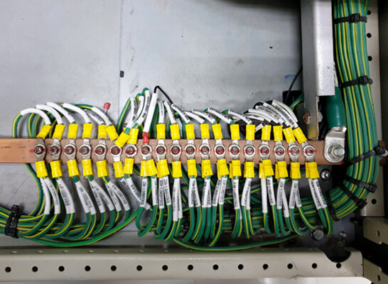
A wire is usually made of a conductive metal like copper. It can be an individual or group of metal strands covered by an exterior sheath. This covering substance is typically made from rubber, thermoplastic, or a vinyl compound. The wire only has a heat-shrunk covering or jacket around the conductive strands. Several of these individual covered wires bond with tie wraps or similar banding material to make up a wiring harness.
Wire harnesses can be advantageous since they are smaller, lighter, and typically less costly than cable assemblies. However, these are inadequate replacements for cable assemblies regarding protection against environmental threats. Wires are partially insulated and secured, making installing harder around various obstacles. Wire harnesses are often used in applications with exterior shells (enclosures) protecting the wires. Primarily found inside products and equipment, such as computers, medical equipment, teller machines, and automation control systems.
Cable Assembly
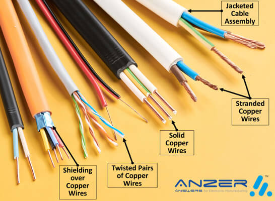
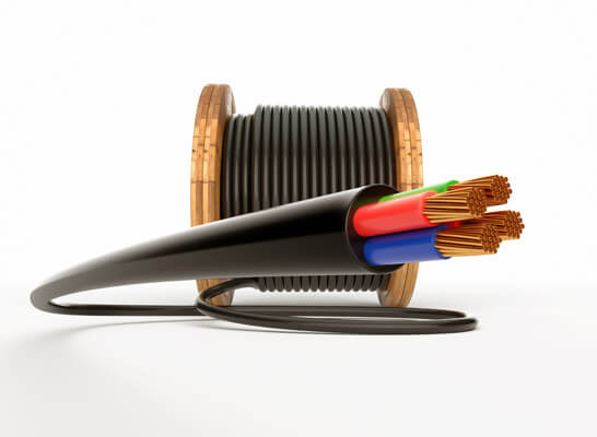
A cable assembly also comprises a set of wires. It differs from a wire assembly in that there is an additional cover or sheathing on the exterior of the cables (group of wires). In the cable assembly, the outer sheathing protects the assembly and the wires from dampness and moisture, highly elevated temperatures, friction/vibration, and other environmental exposures. This makes it especially useful for outdoor applications being resistant to the elements. For this reason, cable assemblies are often used in industries where the cables will be exposed to factors such as aerospace, mining equipment, outdoor lighting, and vital security installations.
Cable assemblies are frequently preferred over wire harnesses because they are tightly bundled. This can make it easier to channel cables in and around equipment. Connectors can also be over-molded with the covering to enhance their protective qualities. The disadvantage of assembled cables is that they can be oversized and heavier. The added shielding layer also comes with a higher price for these benefits.
Wiring Harness or Cable Assembly
An excellent way to think of wiring harnesses is a low-cost electrical unit that keeps electric cables and wires organized. An individual jacked wire from a wire harness can be removed. A cable assembly has multiple wires bundled collectively by a single exterior sleeve. It appears as only one thick wire, such as the interconnect cable between a computer and a printer.
Wire Termination Methods
Wire termination methods refer to connecting the end of an electrical wire to a terminal or a connection point to establish a secure and reliable electrical connection. At ANZER we consider terminations as a crucial step in wiring and electrical installations, as it ensures that electrical current can flow effectively and safely between components or devices.
Termination can take various forms depending on the application and the connection type. Some common methods of wire termination include:
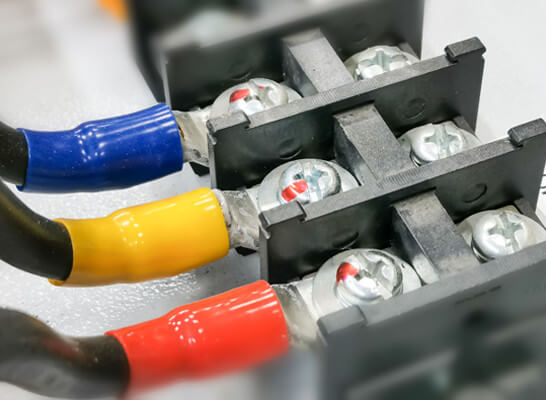
- Screw Terminal: Wires are stripped of their insulation and inserted into a terminal block. A screw is then tightened to secure the wire, creating a mechanical and electrical connection.
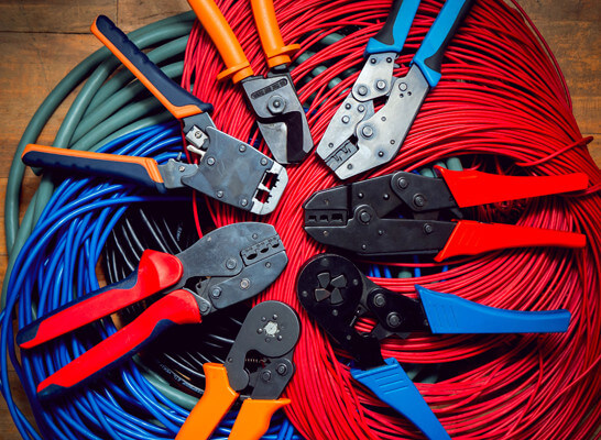
- Crimp Terminal: A crimp terminal or connector is attached to the stripped end of a wire using a crimping tool. This method creates a secure connection by compressing the terminal around the wire.
- Soldering: Soldering involves melting a metal alloy (solder) onto the stripped end of a wire and the terminal or component it is being connected to. This creates a solid, conductive connection.
- Push-In Terminal: Wires are stripped and inserted directly into a terminal without screws or crimps. The terminal’s design ensures that the wire is held securely in place.
- Insulation Displacement Connector (IDC): IDC terminals are commonly used in applications like modular connectors and ribbon cables. They pierce the wire’s insulation to contact the conductor underneath.
- Wire Nut: Wire nuts are twist-on connectors that are commonly used to connect multiple wires together. They have internal threads that twist around the stripped wires, creating a secure connection.
- Lug Terminal: Lug terminals are used for larger wires and cables. They often have a hole or stud that can be connected to a bolt or screw for a solid mechanical and electrical connection.
The choice of termination method depends on factors such as the type of wire, the application’s electrical requirements, the environment in which the connection will be used, and the tools and materials available. ANZER engineers know that proper termination is essential to ensure electrical safety, prevent signal degradation, and maintain the electrical system’s integrity.
Wiring Harness Wire Gauges
Wire gauges used in a wiring harness typically range from around 24 AWG (American Wire Gauge) to 8 AWG, with 24 AWG finer and 8 AWG thicker. While ANZER has used larger and smaller gauges of wire, these tend to be most common. The choice of wire gauge depends on factors like the current-carrying capacity, voltage drop, and the specific application’s requirements. Thinner gauges are suitable for low-current signal wires, while thicker gauges are used for higher-current power distribution. Remember that these ranges can vary based on the specific industry and application. The AWG lists are for single, solid, and round conductors. For stranded wire the cross-sectional area of the equivalent solid conductor is used to determine its gauge. Interestingly, there are modest gaps between the wire strands, so the stranded wire will a have a somewhat larger overall diameter when compared to a solid wire with the same AWG.
Pull Testing PCB-to-Wire Connections
A pull test for PCB-to-wire connections is a mechanical test used to determine the strength of the connection between a printed circuit board (PCB) and a wire or cable. This test ensures that the soldered or crimped connections between the wires and the PCB pads are strong enough to withstand mechanical stresses, such as pulling or tugging, that the assembly might experience during its intended use.
Here’s a general overview of how a PCB-to-wire connection pull test is conducted at ANZER:
- Sample Preparation: Prepare a sample of the PCB assembly with the wires or cables attached to the appropriate pads on the PCB. The wires could be soldered or crimped, depending on the type of connection used.
- Fixturing: The sample assembly is securely mounted in a fixture or holder that can apply a controlled pulling force to the wires. The fixture should mimic the real-world conditions under which the assembly will be subjected to mechanical stress.
- Pulling Mechanism: A pulling mechanism is used to apply a controlled force to the wires. This force is usually applied perpendicular to the PCB surface, simulating a scenario where the wires might be tugged or pulled.
- Force Measurement: During the pull test, the force applied to the wires is measured using load cells or force gauges. This measurement helps determine the maximum force the connection can withstand before failing.
- Test Procedure: The test procedure involves gradually increasing the pulling force at a controlled rate until the connection separates from the PCB or reaches a predetermined failure threshold. The force at which the connection fails is recorded.
- Data Analysis: The recorded force data is analyzed to assess the strength of the connection. The maximum force reached before failure indicates the connection’s mechanical reliability.
- Pass/Fail Criteria: Pass/fail criteria are established based on the specific requirements of the PCB assembly. The assembly might be deemed acceptable if the connections can withstand a specific minimum force without failing. The criteria could be defined by industry standards or the application’s specific requirements.
- Reporting: A test report is generated, documenting the test procedure, the equipment used, the test results, and whether the assembly passed or failed the pull test.
It’s important to note that the specific details of the pull test can vary based on factors such as the type of PCB-to-wire connections, the intended application of the assembly, industry standards, and regulatory requirements. Manufacturers like ANZER often perform these tests during the quality control process to ensure the reliability of their products.
Proper Wire Stripping
Wire stripping is a process used to remove the outer insulation or covering from an electrical wire to expose the inner conductive metal. This is often done when working with electrical or electronic components, such as connecting wires to terminals, soldering connections, or making repairs.
The main purpose of wire stripping is to expose the conductive core of the wire so that it can be easily connected to other wires, terminals, or components. The exposed metal conductor can then be twisted, soldered, crimped, or connected in another way to create a reliable electrical connection.
There are various tools designed specifically for wire stripping, each with its method of operation:
- Manual Wire Strippers: These tools typically resemble pliers and have notched or serrated jaws that grip the wire’s insulation. The jaws cut into the insulation by squeezing the handles while leaving the conductor intact. After cutting, the insulation can be pulled away, leaving the conductor exposed.
- Automatic Wire Strippers: These tools are often used for larger quantities of wires. They usually feature adjustable settings to accommodate different wire diameters. You insert the wire into the tool, and it automatically grips, cuts, and removes the insulation when you squeeze the handles.
- Knife or Blade Method: This method involves using a sharp knife or blade to carefully cut the insulation without damaging the conductor inside. It requires more skill and caution compared to using dedicated wire stripping tools.
When stripping wires, it’s essential not to cut into the metal conductor or damage its integrity. Accidentally damaging the conductor can result in unreliable connections, increased electrical resistance, or even short circuits, which could be hazardous.
Different wires have various insulation materials, such as plastic, rubber, or thermoplastic compounds. The appropriate stripping method and tool will depend on the type and size of wire you are working with. At ANZER we always follow safety guidelines and take precautions when working with electrical wiring to prevent injury and ensure proper connections.
IPC A-620 Certification Importance
IPC-A-620 is a certification program developed by the Association Connecting Electronics Industries (IPC) that focuses on the requirements and acceptance criteria for cable and wire harness assemblies. This standard outlines the criteria for designing, manufacturing, and inspecting cable and wire harnesses used in various electronic devices and systems. Our team of veteran assembly personnel have these and other certifications. The certification training for IPC-A-620 covers a range of topics related to cable and wire harness assembly, including:
- Design and Assembly: The training covers best practices for designing cable and wire harnesses to ensure proper functionality, safety, and reliability. It also addresses techniques for assembling components, routing wires, and connecting cables.
- Materials and Components: Participants learn about the different types of materials and components used in cable and wire harness assemblies. This includes understanding the properties of different cables, connectors, terminals, and insulating materials.
- Soldering and Crimping: The training includes instruction on proper soldering and crimping techniques for joining wires, connectors, and terminals. Ensuring strong and reliable connections is critical for the performance of electronic devices.
- Inspection and Testing: IPC-A-620 emphasizes the importance of inspection and testing to ensure the quality of cable and wire harness assemblies. Participants learn about various inspection methods and criteria for identifying defects and ensuring compliance.
- Documentation and Standards: The training covers the documentation requirements for cable and wire harness assemblies, including labeling, markings, and record keeping. It also highlights relevant industry standards and regulations.
- Quality Control and Continuous Improvement: Participants learn about quality control processes and how to implement continuous improvement initiatives to enhance the efficiency and effectiveness of cable and wire harness assembly operations.
The IPC-A-620 certification training is typically conducted by certified instructors who are experts in the field of electronics manufacturing. After completing the training and passing a comprehensive exam, participants can earn IPC-A-620 certification, which is recognized by electronics manufacturers, suppliers, and other stakeholders as a mark of expertise in cable and wire harness assembly.
Wire & Cable Blog

Understanding Ethernet Cable Categories
Ethernet cable categories are based on their performance and specifications. The Electronic Industries Association (EIA) and the Telecommunications Industry Association (TIA) define the categories. Each category is designed to support different data transfer rates and applications. Here are the commonly used Ethernet cable categories: It’s...

Single-Pair Ethernet: Industrial & Vehicle Application Advantages
Single-Pair Ethernet (SPE) is a subset of Ethernet technology designed to transmit data and power over a single twisted pair of copper wires. It is particularly relevant in the context of automotive and industrial applications where lightweight, cost-effective, and space-efficient communication solutions are essential. SPE...

Q: What is Ethernet Powerlink
A: Ethernet Powerlink (EPL) is a real-time communication protocol used in industrial automation applications. It is designed to enable communication between various devices in a control system, such as programmable logic controllers (PLCs), sensors and actuators, and other automation components. Critical features of Ethernet Powerlink...
