Electronic Telecommunications: Systems, Components, and Manufacturing
Electronic telecommunications enables voice, data, video, and other information to move between connected devices and networks. Behind every reliable communication system are electronic components, circuit boards, transmitters, receivers, network interfaces, and supporting hardware that must work together as designed.
For OEMs developing telecommunications equipment, understanding these electronic systems is only part of the challenge. The manufacturing process also matters. PCB assembly, component sourcing, inspection, testing, wiring, and system integration all influence whether an electronic product can be manufactured consistently and perform reliably in its intended application.
ANZER USA supports B2B electronics manufacturing from its Akron, Ohio facility, with capabilities spanning PCB assembly, electronic contract manufacturing, prototyping, wire harness and cable assembly, box build assembly, and testing.
What Is Electronic Telecommunications?
Electronic telecommunications is the transmission of information between two or more locations using electronic communication systems and wired or wireless networks.
These systems convert information into signals, transmit those signals through a suitable medium, and recover or process the information at the receiving end.
Depending on the application, electronic telecommunications can involve electrical signals carried over copper conductors, optical signals transmitted through fiber-optic infrastructure, or radio waves used for wireless communication.
Common examples include:
- Wired telephone and data communication systems
- Cellular and wireless networking equipment
- Wi-Fi routers, gateways, and access points
- Fiber-optic communication equipment
- Satellite communication systems
- Network switches and interface equipment
- Industrial communication and monitoring systems
The exact architecture varies by application. A wireless gateway, for example, has different radio-frequency requirements from a wired network interface, even though both depend on electronic circuits, power management, signal processing, and reliable interconnections.
How Does an Electronic Telecommunications System Work?
A telecommunications system typically combines several functions to move information from a source to a destination.
1. Signal generation and input
The system receives or generates information, such as voice, sensor data, digital messages, or video. Electronic circuitry converts the input into a signal that the system can process.
2. Signal processing and encoding
The signal may be filtered, amplified, encoded, or otherwise processed before transmission. The specific functions depend on the communication technology and the product design.
3. Transmission
The processed signal travels through a communication medium. That medium may be copper wiring, fiber-optic cable, or a wireless radio-frequency link.
4. Reception and recovery
A receiving circuit detects the incoming signal and processes it to recover the transmitted information. Additional circuitry may handle filtering, decoding, error correction, or interface conversion.
5. Network routing and system coordination
In networked applications, switching and routing functions help direct information between connected devices and network segments.
Power supplies, connectors, firmware, thermal management, shielding, and mechanical enclosures support these functions throughout the system.
For product developers, the practical takeaway is that communication performance depends on more than an individual component. The complete electronic assembly must meet its electrical, mechanical, thermal, and environmental requirements.
Key Components Used in Telecommunications Electronics
Telecommunications products vary considerably, but several component categories appear frequently across communication equipment.
| Component or subsystem | Primary function | Manufacturing consideration |
|---|---|---|
| Printed circuit boards (PCBs) | Provide electrical connections and mounting for components | Layout, layer structure, clearances, and fabrication requirements |
| Integrated circuits | Perform processing, control, switching, and communication functions | Package compatibility, sourcing, placement, and soldering requirements |
| Transmitters and receivers | Send and detect communication signals | Application-specific electrical and RF requirements |
| Antennas and RF interfaces | Support wireless signal transmission and reception | Interface integrity, placement, and mechanical integration |
| Power management circuits | Convert and regulate electrical power | Thermal considerations, component selection, and electrical testing |
| Connectors and cables | Carry power and signals between assemblies | Pinout accuracy, retention, routing, and connection integrity |
| Network interfaces | Connect equipment to wired or wireless networks | Interface compatibility and functional verification |
| Enclosures and thermal components | Protect and support the electronic assembly | Mechanical fit, heat dissipation, and environmental requirements |
Not every telecommunications product includes every component listed above. The product architecture, operating environment, and design requirements determine the appropriate configuration.
Types of Electronic Telecommunications Systems
Different communication applications place different demands on electronic hardware. Understanding those differences helps OEMs define manufacturing requirements before requesting a quote.
Wired communication systems
Wired systems transmit signals through physical connections, including copper conductors and fiber-optic infrastructure.
Electronic equipment used in these systems may include network interfaces, switching hardware, transmission electronics, power supplies, and control boards.
Manufacturing considerations include connector compatibility, board layout, signal integrity requirements, electrical interfaces, and the testing needed to verify the finished product.
Wireless communication systems
Wireless systems transmit and receive information using radio waves. Examples include wireless gateways, access points, cellular equipment, and other radio communication products.
These products may require RF components, antennas, shielding, specialized connectors, and carefully controlled board layouts.
During product development, engineers should define the required operating bands, interfaces, power characteristics, and verification procedures. The assembly manufacturer should understand the physical and process requirements of the board, while application-specific RF performance must be validated using appropriate engineering methods.
Fiber-optic communication equipment
Fiber-optic systems use light to carry information through optical fiber. Supporting electronic equipment may include optical transceivers, control circuits, power management, monitoring functions, and electrical interfaces.
Manufacturing requirements depend on the design, including component package constraints, connector placement, thermal conditions, and the testing needed to verify electrical and optical functions.
Industrial communication systems
Industrial communication equipment connects controllers, sensors, monitoring devices, and other equipment used in industrial environments.
These products may operate near electrical noise sources, experience temperature changes, or require protection against moisture, dust, and vibration.
OEMs should define the intended operating environment early. That information can influence component selection, PCB design, enclosure requirements, cable routing, coating or potting decisions, and final test procedures.
Why PCB Assembly Matters in Telecommunications Equipment
A telecommunications product may rely on complex integrated circuits, dense component placement, multiple connectors, and interfaces that must operate together. PCB assembly converts the bare circuit board and electronic components into a populated assembly that can be integrated into the finished product.
The assembly process must match the design, component packages, workmanship requirements, and expected production volume.
Surface Mount Technology (SMT)
SMT places surface-mount components directly onto PCB pads. It supports compact layouts and a broad range of electronic component packages.
The process typically includes solder paste printing, component placement, reflow soldering, and inspection.
For telecommunications boards, important considerations can include fine-pitch component placement, solder-joint quality, thermal profiling, component orientation, and the inspection methods appropriate to the assembly.
Through-Hole Technology (THT)
Through-hole components have leads inserted through holes in the circuit board and soldered to conductive pads.
This method is useful for components and connections whose designs call for through-hole mounting. Depending on the assembly, manufacturers may use wave soldering or hand soldering.
Mixed-Technology Assembly
Some telecommunications products combine SMT and THT components on the same board. The manufacturing process must account for component compatibility, assembly sequence, soldering requirements, and inspection access.
OEMs evaluating a manufacturing partner should confirm that the supplier can support the board’s actual assembly requirements, rather than evaluating equipment capability alone.
Learn more about ANZER’s PCB assembly services.
Inspection and Testing for Telecommunications Electronics
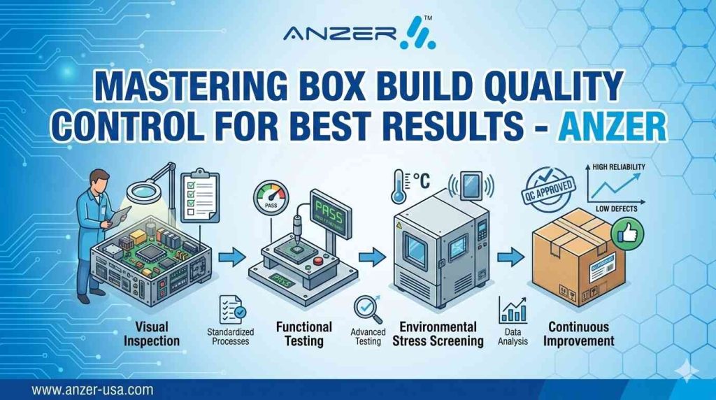
Inspection and testing are different activities. Inspection examines assembly characteristics, while testing evaluates electrical behavior or product functionality according to defined requirements.
The appropriate combination depends on the product design, risk, workmanship requirements, and customer specifications.
| Method | What it helps evaluate | When it may be useful |
|---|---|---|
| Automated Optical Inspection (AOI) | Visible solder-joint characteristics and component placement | Identifying visible assembly defects |
| X-ray inspection | Hidden solder connections and internal joint characteristics | Assemblies containing applicable hidden-joint packages, such as BGAs |
| In-Circuit Testing (ICT) | Electrical connectivity and component-related characteristics supported by the test setup | Boards designed with suitable test access and coverage |
| Flying probe testing | Electrical characteristics using movable probes | Suitable assemblies where a flying-probe approach meets the test requirements |
| Functional testing | Whether the assembly performs specified functions | Verifying behavior against defined product requirements |
| Burn-in testing | Behavior during an extended period of specified electrical and thermal stress | Applications where the product qualification or customer requirements call for it |
No single method detects every possible defect. AOI, for example, cannot independently establish that a complete communication system meets its intended RF performance requirements. Likewise, a successful functional test does not replace all workmanship inspection or required documentation.
OEMs should define acceptance criteria and test coverage before production. This allows the manufacturing team to identify required fixtures, test points, programming needs, and other dependencies before they become schedule or quality problems.
Design for Manufacturability in Telecommunications Product Development
Design for Manufacturability (DFM) is the review of a product design to identify issues that could make manufacturing more difficult, inconsistent, or costly.
For telecommunications electronics, a DFM review can examine:
- Component availability and approved alternatives
- PCB layout and assembly clearances
- Component package and placement constraints
- Soldering and inspection access
- Board handling and depanelization considerations
- Test-point access and electrical test requirements
- Connector orientation and mechanical fit
- Bill of Materials (BOM) accuracy
- Coating or potting requirements, where specified
- Documentation and revision control
A design that functions on an engineering bench may still present assembly or test challenges when production begins. Reviewing these issues before the build gives engineering and manufacturing teams an opportunity to resolve them while design changes are still manageable.
DFM does not replace engineering validation. It complements the product development process by identifying manufacturing concerns that should be addressed before release.
ANZER provides electronic design for manufacturability support to help customers review manufacturing considerations during product development.
From Prototype to Production: Reducing Manufacturing Handoffs
Telecommunications products often go through several stages before production release. A typical development path includes a prototype build, engineering evaluation, design revisions, pre-production validation, and production manufacturing.
Each stage can reveal different issues.
A prototype build may uncover assembly access problems, component sourcing concerns, or unexpected test requirements. A pre-production build can help verify that the revised design and manufacturing process are ready for the intended production conditions.
When the prototype and production processes are handled by different suppliers, manufacturing knowledge and revision history must be transferred carefully.
OEMs can reduce this handoff risk by establishing clear documentation, revision control, test requirements, and acceptance criteria from the beginning.
ANZER maintains a dedicated prototype production line and supports builds from prototype through production, with no minimum order quantity. Its manufacturing capabilities can support projects that require engineering feedback before moving into larger production runs.
For more detail, see prototype PCB assembly.
Box Build Assembly for Complete Telecommunications Products
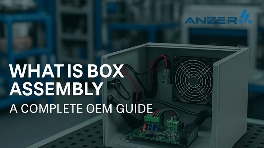
A populated PCB is not always the finished product. Telecommunications equipment may also require enclosures, cables, connectors, mounting hardware, power components, and other subassemblies.
Box build assembly brings the required electronic and mechanical components together into a complete assembly according to the product documentation.
Depending on the design, this can include:
- Integrating populated circuit boards into enclosures
- Installing connectors and mechanical hardware
- Routing and securing wires and cables
- Installing specified subassemblies
- Applying product labels and identification
- Performing defined electrical or functional tests
- Completing final inspection and packaging
The value of system integration is not simply having fewer suppliers. It also requires accurate drawings, clear assembly instructions, controlled revisions, and a defined method for verifying the completed product.
ANZER provides box build assembly services and wire harness and cable assembly to support relevant electronics manufacturing requirements.
Protecting Telecommunications Electronics in the Intended Environment
Some telecommunications products operate indoors in controlled conditions. Others may be installed outdoors, in industrial facilities, or in environments with greater exposure to moisture, dust, temperature changes, or vibration.
The operating environment should be defined during product development because it influences enclosure design, material selection, thermal management, interconnections, and protection requirements.
Conformal coating
Conformal coating applies a protective layer to selected areas of an electronic assembly. Depending on the coating material and application, it can help protect circuits against specified environmental exposures.
The design must identify which areas should be coated and which must remain free of coating, such as certain connectors, test points, or components.
Potting
Potting uses an encapsulating material to surround specified electronic components or assemblies. It may be appropriate where the design requires additional environmental protection or mechanical support.
Potting is not suitable for every product. Material compatibility, heat dissipation, repairability, inspection access, and the intended operating conditions must be considered before it is specified.
ANZER offers in-house conformal coating and potting under controlled environments. These processes should be selected according to the product requirements, not applied as a default to every telecommunications assembly.
How to Select a Telecommunications Electronics Manufacturing Partner
Choosing a manufacturing partner requires more than confirming that the supplier can populate a circuit board. OEMs should evaluate the complete manufacturing scope and how well it matches the product’s technical requirements.
Use the following checklist when evaluating a potential supplier.
| Evaluation area | Questions to ask |
|---|---|
| Assembly capability | Can the supplier support the required SMT, THT, or mixed-technology assembly? |
| Component sourcing | Can the BOM be reviewed for availability, approved alternatives, and sourcing risks? |
| DFM support | Will manufacturing concerns be reviewed before the build begins? |
| Quality requirements | Which quality certifications and workmanship standards apply to the actual product? |
| Inspection | Which assembly defects can the proposed inspection methods detect? |
| Testing | What functional and electrical requirements must the test process verify? |
| Documentation | Are drawings, BOM revisions, assembly instructions, and acceptance criteria controlled? |
| Prototype support | Can the supplier support engineering builds and design iterations? |
| System integration | Can it handle the required wiring, enclosures, and mechanical assembly? |
| Environmental protection | Are coating or potting processes available if the design requires them? |
| Production transition | Can the supplier support the planned move from prototype to production? |
| Domestic manufacturing | Where will the manufacturing operations actually take place? |
The answers should be evaluated against the specific product, its operating environment, production plans, and customer requirements. A supplier’s general capabilities do not automatically establish that every project requirement is covered.
How ANZER Supports Telecommunications Electronics Manufacturing
ANZER USA is a B2B electronic contract manufacturer based in Akron, Ohio, with manufacturing operations in the United States.
The company’s capabilities include PCB assembly, SMT and THT assembly, turnkey electronic contract manufacturing, prototype builds, box build assembly, wire harness and cable assembly, inspection and testing, conformal coating, and potting.
ANZER has more than 33 years of manufacturing experience through its legacy as Western Reserve Controls, 4,000+ completed projects, 200+ customers, and experience across 10+ industries.
For OEMs developing telecommunications-related electronic products, the appropriate manufacturing scope depends on the board design, component requirements, testing needs, enclosure integration, and production plan.
The first step is to establish those requirements clearly. From there, engineering and manufacturing teams can evaluate assembly methods, sourcing considerations, quality controls, and the documentation required for the project.
To discuss a manufacturing requirement, visit ANZER’s electronic contract manufacturing services or request a quote.
Frequently Asked Questions
What is electronic telecommunications?
Electronic telecommunications is the exchange of information over wired or wireless communication systems. It uses electronic equipment to generate, process, transmit, receive, and route signals.
What electronic components are used in telecommunications equipment?
Depending on the product, telecommunications equipment may contain PCBs, integrated circuits, transmitters, receivers, RF components, antennas, power management circuits, connectors, cables, and network interfaces.
Why is PCB assembly important for telecommunications products?
PCB assembly turns a designed circuit board and its components into a populated electronic assembly. Correct component placement, soldering, inspection, and testing help establish whether the assembly meets its manufacturing and functional requirements.
What testing may be required for telecommunications electronics?
Requirements vary by design. They may include AOI, X-ray inspection for applicable packages, ICT, flying probe testing, functional testing, and other application-specific verification. The required coverage should be defined by the product’s acceptance criteria.
Can ANZER support prototype and production electronics manufacturing?
Yes. ANZER supports prototype through production manufacturing and maintains a dedicated prototype production line. It also offers PCB assembly, box build assembly, wire harness and cable assembly, testing, coating, and potting, depending on the project requirements.
Conclusion
Electronic telecommunications depends on more than the transmission of information. The hardware behind communication networks must be designed, assembled, inspected, and tested against the requirements of its intended application.
For OEMs, the manufacturing decision should begin with the product’s technical needs: PCB assembly methods, component sourcing, DFM, inspection, testing, documentation, environmental protection, and system integration.
ANZER USA supports these manufacturing stages from Akron, Ohio. With a defined scope, complete product documentation, and clear acceptance criteria, OEMs can evaluate the right manufacturing approach for their telecommunications electronics program.
Planning a telecommunications electronics project? Contact ANZER USA to discuss your PCB assembly, prototype, or system integration requirements.